An industrial PC can pass a purchasing checklist and still fail at the installation site. The enclosure survives dust, yet the processor slows down inside a hot cabinet. The operating system restarts after a power interruption, yet the last production record is missing. The screen looks clear on a desk, yet an operator cannot use it from the installed angle.
These are integration failures, not problems a faster processor automatically solves. When selecting industrial computers for harsh environments, the engineering task is to define the operating boundary, identify the failure modes that stop work, and prove recovery before fleet deployment.
1. Start with the cost of a failed task
Write down the business event the computer supports: confirming a picked item, recording an inspection, displaying a machine alarm or collecting process data. Then ask what happens if that event is delayed, duplicated or lost. An unavailable dashboard and a missing traceability record have different consequences. They should not share an acceptance criterion simply because they run on the same hardware.
Create a failure register with five fields: trigger, visible symptom, operational consequence, recovery owner and evidence required to close the issue. For example, “network unavailable” is a trigger; “operator repeats a submission because no acknowledgement appears” is the symptom. The resulting duplicate record is the application failure that must be prevented.
2. Translate the environment into measurable limits
A factory-wide temperature reading is not an adequate specification for a computer mounted beside a drive or inside a sealed cabinet. Measure at the intended installation point during a representative operating cycle. Record the mounting orientation, clearance, nearby heat sources and application load with every reading.
Thermal performance depends on the heat path. A fanless enclosure removes a moving component, but heat still has to travel through the chassis into its surroundings. A higher-power CPU may improve short benchmarks while reducing sustained performance in a constrained installation. Compare the complete application at thermal steady state, including its response-time distribution, rather than comparing processor names.
Manufacturer mounting instructions matter. As one documented example, Beckhoff explains that incorrect orientation or insufficient clearance can cause overheating. Those device-specific limits cannot be transferred to another model; obtain the manual for the actual candidate.
Protection ratings answer a narrower question than buyers expect
IEC 60529 defines enclosure protection classifications. An IP designation is not a blanket statement about every environmental stress. Ask which surfaces are covered, whether connectors must be capped, and what mounting conditions apply. Do not infer chemical resistance, corrosion resistance or suitability for condensation from an IP number.
If a device moves between a cold storage area and warmer humid air, ask the supplier how condensation is addressed and what acclimatization procedure applies. If cleaning chemicals are used, list the substance, concentration and contact time. “Waterproof” is too vague to approve either scenario.
3. Choose the architecture by maintenance consequences
| Decision | When it can fit | Trade-off to verify |
|---|---|---|
| Integrated panel PC | A fixed operator station with a defined mounting position | A display fault may require replacing or servicing the whole unit. Check access and spare-unit strategy. |
| Box PC with separate display | Processing hardware needs a protected location or independent servicing | Additional display, power and touch cables create more installation and diagnostic work. |
| Vehicle-mounted platform | The work point travels with a vehicle | Validate the bracket, cable retention and power behavior together with the vehicle integration team. |
List every peripheral and its actual requirements. “Serial port” does not identify the electrical interface, pinout, isolation requirement or application protocol. “USB available” does not establish that the required driver runs on the chosen operating system. Ask the integrator to demonstrate the exact scanner, controller or measurement device used in production.
4. Specify power recovery and data integrity separately
A successful reboot proves only that the machine can restart. It does not prove that an acknowledged transaction survived. Define a recovery time objective: the permitted interval until the application is usable again. Separately define a recovery point objective: how much data loss, if any, the workflow can tolerate.
For an inspection application, a useful state sequence is: input captured, record committed locally, submission sent, server acknowledgement received. The user interface should distinguish “saved locally” from “synchronized.” If the connection fails after the server processes a request but before the client receives the reply, retrying with the same transaction identifier lets a correctly designed server detect the duplicate.
A transactional database is one part of this design. Its guarantees depend on configuration and the storage stack. SQLite documents its crash-recovery mechanisms and assumptions; simply choosing a database does not replace testing the deployed software and hardware combination.
Power hold-up or a managed UPS may allow an orderly shutdown, but size it around the measured shutdown workload and verify its signal integration. A watchdog can help recover an unresponsive process, but repeated resets can also hide the original fault. Preserve diagnostic logs and define an escalation threshold.
5. Turn the pilot into an acceptance test
Use a spare test unit and a controlled environment for fault injection. Agree the method with the responsible engineering team. The following is an example acceptance framework, not a universal certification procedure or a claim about any product.
| Test | Record | Example decision rule |
|---|---|---|
| Sustained application load at the expected local temperature | Ambient conditions, application latency, resource use and errors | The 95th-percentile response time remains within the workflow target agreed before testing. |
| Planned network interruption and reconnect | Local queue depth, transaction identifiers and server totals | All committed test records reconcile; no duplicate business transactions remain. |
| Controlled restart at different transaction stages | Last acknowledged record and time to a usable application | Recovery meets the agreed data-loss and restart limits. |
| Peripheral disconnect and reconnect | Port identity, driver errors and operator recovery steps | The application detects the fault and follows a documented recovery path. |
| Replacement-unit exercise | Time for mounting, image restore, configuration and functional check | A technician can restore service using the written procedure and approved spares. |
Test duration should follow the duty cycle and risk. A short pilot cannot prove a multi-year failure rate. It can reveal repeatable integration faults and produce a baseline for monitoring the deployment.
6. Calculate TCO without inventing savings
Use: lifecycle cost = purchase + integration + deployment + support + replacement + attributable downtime. Avoid counting the same outage under both lost production and labor unless those costs are genuinely separate. Include the cost of keeping a spare, maintaining software images and qualifying substitute components.
Illustrative budget scenario, not measured customer results: suppose a stronger integration package costs an extra $180 for each of 40 terminals, plus $2,000 for validation. The extra investment is $9,200. If logs later show that it prevents four terminal-related line stoppages per year, each lasting 45 minutes, and finance accepts $1,200 per hour as the relevant line-loss estimate, modeled annual avoidance is 4 × 0.75 × $1,200 = $3,600. Simple payback is about 2.6 years, excluding financing and ongoing cost differences.
The conclusion changes sharply with the assumptions. At two avoided stoppages per year, payback becomes about 5.1 years. If the terminals do not stop production, use technician time, rework or delayed transactions instead of a line-loss rate. Procurement should request evidence for the failure frequency before accepting the business case.
7. Build a procurement package that engineering can sign
- Operational baseline: workflow, failure register, actual duty cycle and recovery objectives.
- Installation definition: drawings, local environment measurements, cable plan and power requirements.
- Configuration record: exact hardware revision, operating system, application build and peripheral drivers.
- Acceptance evidence: test steps, raw logs, exceptions, corrective actions and named approvers.
- Lifecycle agreement: support scope, replacement process, component-change notification and a revalidation trigger.
Release a small, monitored batch before the full rollout. Record incident categories and restoration times consistently. Otherwise the organization cannot tell whether a later improvement came from the computer, network, software or operator training.
Where Emdoor fits in the evaluation
Once these requirements are defined, the Emdoor industrial computing portfolio provides panel PC, embedded box PC, touch display and vehicle-computing categories to evaluate. Treat each as a candidate architecture, then ask for documentation and a test configuration matched to the project. Confirm model-specific protection, temperature limits, interfaces and operating-system support in writing.
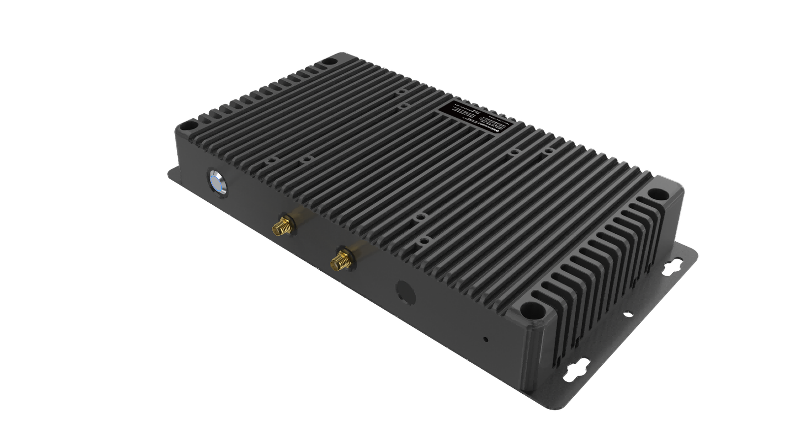
For fixed production stations, review the manufacturing application overview alongside the acceptance matrix above.
A productive discussion starts with the failure register and acceptance matrix. Bring those documents, an application image and representative peripherals to the Emdoor project team. The objective is a configuration that passes your workflow tests and can be restored by your maintenance team—not a longer specification sheet.