

Control devices, data and updates from depot to edge.
A vehicle computer only creates value when its operating image, interfaces, connectivity and recovery path work as one system. This software framework helps teams deploy repeatable configurations, keep field workflows focused and maintain distributed devices without turning every service event into a site visit.

Deploy once. Operate consistently. Maintain without surprises.
The hard part is not installing an application. It is keeping the same behavior across vehicles, shifts, operating systems and changing network conditions.
Standardize the endpoint
Define the OS image, drivers, application package, access policy and interface profile before the first vehicle enters service. A repeatable baseline reduces commissioning drift.
Protect the workflow
Keep drivers and operators inside the approved task flow. Map keys, scanners and peripherals to the application so the interface matches the job, not a generic desktop.
Recover with evidence
Collect device health and application logs, separate network faults from hardware faults, and use phased update rings with a rollback route for field recovery.
Functions that solve field-service problems
Choose only the modules the project needs. The final capability depends on the selected device, operating system, interfaces and customer application.
Fleet & device management
Organize devices by model, vehicle group, depot or customer account and apply the correct policy to each group.
- Inventory and policy groups
- Configuration status
- Role-based administration
Kiosk & workflow control
Launch the approved application at startup, restrict unintended settings and present a simple recovery route to authorized technicians.
- Single or multi-app mode
- Controlled system access
- Shift-ready startup
Keys, scanners & peripherals
Map physical keys, barcode input and serial or USB peripherals to the actions that operators use most often.
- Key mapping profiles
- Scanner data routing
- Peripheral validation
Vehicle interface layer
Normalize data from project-specific CAN, RS-232, RS-485, GPIO or USB interfaces before it reaches the business application.
- Interface health checks
- Data format rules
- Event and alarm routing
GNSS & offline synchronization
Use store-and-forward logic for routes where 4G or 5G coverage is uneven. Timestamp records locally and reconcile them after connectivity returns.
- Position and time context
- Local transaction queue
- Duplicate-safe resynchronization
Controlled OTA updates
Separate pilot, limited and fleet-wide releases. Schedule downloads around shifts and power state, then verify the new version before closing the change.
- Staged deployment rings
- Package verification
- Rollback planning
Remote diagnostics
Capture useful evidence before dispatching a technician: software version, storage, temperature, connectivity and recent application events.
- Health snapshot
- Log collection
- Fault classification
Security configuration
Apply least-privilege accounts, application allowlists, certificate handling and update controls that fit the customer’s IT process.
- Access boundaries
- Credential lifecycle
- Change audit trail
Project customization
Align boot behavior, branding, application packaging, regional settings and acceptance tests with the deployment standard.
- Golden image definition
- Factory provisioning
- Handover documentation
Keep the vehicle productive when the connection is imperfect.
A reliable design treats the network as a variable, not an assumption. Critical operator actions are acknowledged locally, records are queued with timestamps, and synchronization resumes with clear conflict rules.
This architecture also shortens diagnosis: teams can see whether a missing record began at the sensor, interface, application, device or cloud layer.
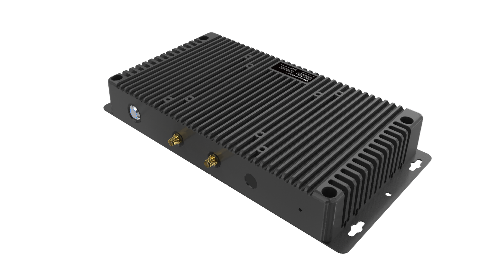
One framework, different operational priorities.
Vehicle and industrial projects share a need for predictable endpoints, but their failure modes differ. Start with the operating process, then select the hardware, OS and software controls that support it.
Review compatible platforms in Vehicle PCs, Industrial PCs and our Transportation solution.
A five-step rollout that exposes risk early
Move from a written operating model to a monitored pilot before scaling. Each gate should produce evidence that the next stage is safe.
Map the operation
Document users, shifts, data flows, interfaces, coverage gaps, power states and recovery owners.
Freeze a baseline
Record the device SKU, BIOS or firmware, OS build, drivers, applications and configuration profile.
Test failure modes
Simulate lost network, abrupt power-off, low storage, bad packages and peripheral disconnection.
Pilot by cohort
Start with representative vehicles and shifts. Measure task completion, sync delay, faults and support effort.
Scale with control
Use deployment rings, change records, rollback criteria and lifecycle ownership for every release.
Turn the deployment requirement into a testable system.
Share the vehicle, peripherals, application, network conditions and maintenance process with the Emdoor IPC team.